Pictures of K3SIW LF Receive Loops
The LOWDOWN, August 2013
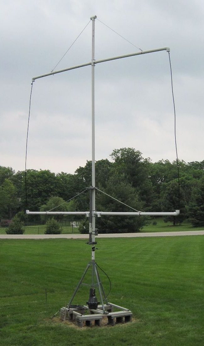
Photo of the 10 Foot Loop
10 Foot Loop Construction
In this page are a photo and diagram of my version of a 10' shielded loop (above), and the same for the 4' shielded loop (below). The former uses 1.5" PVC while the latter can get by with 1.25" PVC. I purposely do not cement the sections together so I can easily dismantle them for transport or storage. To strengthen the 10' loop support, I use UV-resistant rope and hose clamps around joints. I also include an offset metal brace. None of that is needed by the 4' loop.
The coax used by the 10' antenna is not critical since the PVC provides reasonable support for the horizontal runs. I used LMR400 coax with N-male connectors to mate with the preamp and N-female connectors at the top. The top left and top right LMR400 coax connects to a 6" piece of RG-8 with N-male connectors on each end. The RG-8 shield is broken in the center and taped to weatherproof and keep separated.
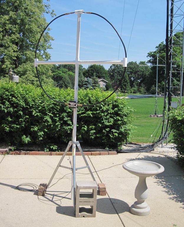
Photo of the 4 Foot Loop
4 Foot Loop Construction
Coax for the 4' antenna needs to be stronger (stiffer) to maintain a circular shape. I used two 6' Andrew 1/2" Heliax jumpers, again connected by a short length of RG8 at the top with the shield broken.
Of course, one could instead maintain the architecture of the 10' antenna and just downsize it to a 4' square. In that case even RG-58 would suffice.
Remember to tape or otherwise seal the shield cut in the top center coax of both antennas. Center the break as best you can, as symmetry of the gap with respect to ground is the key to good noise reduction.
I got my 4-way Tees at Menards, a local hardware store, but they may be harder to find in smaller towns, or you may have to ask for them by an alternate name. Fortunately, Home Depot and Lowes carry them, too. For example, see www.homedepot.com and use the words "PVC cross" in the search box.
I've made a couple of screenshots for performance comparison of the 10' loop to my Clifton Labs e-probe, using my SDR-IQ centered at 310 kHz with a span of 5 kHz. The relatively close DGPS station at Rock Island, IL is on 311 kHz. Also coming through is the Clark, SD station on 309 kHz. The station on 310 kHz (Whitney, NE) is just barely noticeable with the e-probe but easily detectable with the 10' loop. These can be seen through links at the bottom of this page.
Naturally, both of the antennas need a preamp and DC inserter. The ones described by Steve, VE7SL at http://members.shaw.ca/ve7sl/burhans.html work great. He was also the inspiration for doing the antennas in the first place.
Updated Burhans/VE7SL Loop Preamp Schematic
Photos and text © 2013 Garry Hess, all rights reserved. Obtain the author's permission before using elsewhere. HTML implementation © 2013 by John Harrold Davis. This document must NOT be mirrored on any other server.
www.lwca.org
|